69 Barracuda FB. The next evolution

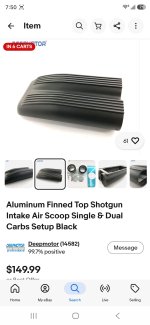
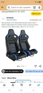
FWIW, these are a few of the parts I ordered today.

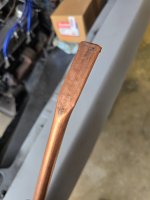
I couldn't find a solid piece of copper flat bar, so I picked up a 1/2" copper grounding rod from Home Despot. I'll hammer one end flat-ish and leave enough length to have room to hold onto it.
 

Attachments

  • Screenshot_20261028_194132_eBay.jpg
    Screenshot_20261028_194132_eBay.jpg
    198.7 KB · Views: 2
  • Screenshot_20261028_195025_eBay.jpg
    Screenshot_20261028_195025_eBay.jpg
    190 KB · Views: 2
  • Screenshot_20261030_171216_Amazon Shopping.jpg
    Screenshot_20261030_171216_Amazon Shopping.jpg
    218.4 KB · Views: 2
  • Screenshot_20261030_171246_Amazon Shopping.jpg
    Screenshot_20261030_171246_Amazon Shopping.jpg
    255.5 KB · Views: 2
I honestly didn't know that mineral spirits would do that to rubber since I had never used it for parts cleaning before. I knew that carb cleaner would do that, so they must have similar chemistry I guess.
It's the oil that does it. Brake fluid is mostly alcohol.
Tomorrow I need to find a thick piece of copper to use as a backer for filling those other inner fender holes with weld.
Find a piece of 3/4" water pipe and hammer it flat. You can clamp it or you can use the other end like a handle to hold it in place where you can't. Um, I guess I'm too late.
 
Yea, I'm going to return the ground rod. I realized it was just copper coated steel. I'll give that copper pipe trick a try.

I didnt realize I was out of grinding wheels, so I went back to the flap discs for the weld clean up. We were getting rain today, so I did the weld grinding kinda quick and painted the bare area to keep the rust away.

After that, I jacked the car back up so I could get started on the fuel lines. My jack stands were too short to have enough room to work with the long aluminum lines under the car, so I picked up a pair of the taller 6 ton stands from HF. Good enough now. The rear ends of the lines are now bent to shape, up to the firewall.

All that is left is to bend the lines around the blower motor, route the lines to the regulator ports, attach the AN ends and hook the lines up. After the lines shape and routing are sorted out, I still need to install rivets in the frame rail and firewall so I can secure the lines in place with P-clamps.

Pics will come later.

EDIT: I forgot to add that today I also ordered a two bolt aluminum brake master cylinder from the LPS, and got an A-body offset M/C adapter from Dr Diff. I'm planning ahead for when I drop the big block in the car. The 400 B block "shouldn't" need the offset adapter, but I plan on using aftermarket valve covers, so better safe than sorry.
 
Last edited:
Yea, I'm going to return the ground rod. I realized it was just copper coated steel. I'll give that copper pipe trick a try.

I didnt realize I was out of grinding wheels, so I went back to the flap discs for the weld clean up. We were getting rain today, so I did the weld grinding kinda quick and painted the bare area to keep the rust away.

After that, I jacked the car back up so I could get started on the fuel lines. My jack stands were too short to have enough room to work with the long aluminum lines under the car, so I picked up a pair of the taller 6 ton stands from HF. Good enough now. The rear ends of the lines are now bent to shape, up to the firewall.

All that is left is to bend the lines around the blower motor, route the lines to the regulator ports, attach the AN ends and hook the lines up. After the lines shape and routing are sorted out, I still need to install rivets in the frame rail and firewall so I can secure the lines in place with P-clamps.

Pics will come later.

EDIT: I forgot to add that today I also ordered a two bolt aluminum brake master cylinder from the LPS, and got an A-body offset M/C adapter from Dr Diff. I'm planning ahead for when I drop the big block in the car. The 400 B block "shouldn't" need the offset adapter, but I plan on using aftermarket valve covers, so better safe than sorry.
The 400 in my duster (same engine compartment as a 69 cuda) fit OK on the drivers side. It came with T-handles in all the VC bolt holes except the rear corners so I would sneak a 1/4" swivel in there to unbolt it.

The driver's side VC would come out with a little forethought (stock rockers) but there was basically no way to get it out on the passenger side without losing your mind over the blower motor. So I just took the heater box out. Don't need that anyway.

Two cents, worth < 0 in the current economy.

FWIW, I hate t-handles. I've got 10 here from that engine, enough for a smallblock. I tried to give them away to a youtuber who just loves the things, and was ignored for my trouble. I used the @ sign and everything. Oh well. So here they are, free for the asking. Anyone ... PM me if you will use them.
 
I already have a set of stock type VC bolts to replace those T-handle ones. I've never been a fan of those things.

M/C arrived at the LPS today, but I can't do anything with it until the adapter arrives. For now I removed the old M/C so I can clean up the firewall before the new parts go on.

I picked up copper tubing today, but it's thinner than I wanted. To fix that, I picked up some twisted copper wire, unbound the strands and laid the individual wires inside the tube before flattening it. The wire goes inside the tube past the bend, and out to the end of the open end. I folded the open end over and smashed it onto on itself to crimp it. The bend and crimp was done to lock the wires in place.

And as promised, here's a couple pics from yesterday's work.
 

Attachments

  • 20261101_143300.jpg
    20261101_143300.jpg
    2.2 MB · Views: 10
  • 20261101_144732.jpg
    20261101_144732.jpg
    1.4 MB · Views: 11
  • 20261101_144740.jpg
    20261101_144740.jpg
    1.5 MB · Views: 8
  • 20261101_143216.jpg
    20261101_143216.jpg
    2.4 MB · Views: 8
  • 20261101_143248.jpg
    20261101_143248.jpg
    2 MB · Views: 11
Last edited:
You tried a lot harder than I did - me, a hammer, a vise, and a piece of pipe. I used 3/4", probably hot water gauge, and it worked great. Nothing wrong with doing more though.
 
Rainy day here, so today I mostly ran errands.

The front brake parts arrived today. I didn't have any bearing grease on hand, so I picked up some while I was out. I also didnt have any actual caliper paint, and there wasn't any in stock at the LPS, so that got ordered while I was there.

When I got back home, I cleaned up the caliper, the one with the ballooned out seal. It got a cosmetic makeover at the same time. I cut off the ugly rectangular casting boss on top, and then smoothed over the top and outside surfaces with the flap wheel. It's just a cosmetic effort, and will make it look much better, especially after paint.

I'll need to replace the bleeder screw, as this one was stuck and I destroyed the hex getting it off with vise grips. The piston was also seized in the caliper body. To get it out, I had to get midevial on it. I grabed the dust seal groove with vise grips, heated the caliper body with a mapp gas torch, and then beat downward against the vise grips with a hammer. After a few tries back and forth between the heat and the hammer, I was finally able to get the piston to pop free.

More to come...
 

Attachments

  • 20261102_184229.jpg
    20261102_184229.jpg
    1,003.7 KB · Views: 2
  • 20261102_184153.jpg
    20261102_184153.jpg
    1.7 MB · Views: 2
Cleaned the shipping oil off the new rotors with brake cleaner, masked off the bearing areas and the pad wear surfaces. Then I gave them a coat of silver caliper paint.

The disassembled caliper got a more thorough de-crusting all over, as well as more exterior deburring and smoothing. It was then masked off and painted silver.

While it was still getting painted, I set the wet caliper on top of the vise anvil to readjust my grip. Gravity chose the exact split second I released my fingers to exert itself on the caliper and draw it down to the grinding grit covered garage floor. NGL, wordy dirds were uttered, at a possibly (very likely) excessive volume given my proximity to the open garage door.

Annnd... that seemed like a good place to stop for today. FML.
 

Attachments

  • 20261104_162112.jpg
    20261104_162112.jpg
    1.2 MB · Views: 2
  • 20261104_172512.jpg
    20261104_172512.jpg
    1.1 MB · Views: 2
I decided to not let the day end with a L, so I went back out to the garage and went to work on the fuel lines.

I split the aluminum lines with a tubing cutter at the front where they make the bend to start going up the firewall. Then I screwed the fittings together at the rear section of the lines and temporarily zip tied the front half of the lines to the subframe connector. About every foot I stuck a piece of tape on the frame and then put a mark between the fuel lines with a sharpie. The fuel lines were moved out of the way so I could drill holes on the tape lines for the rivnuts. I had to remove the shock to get access for the rivnut tool, at the top of the arch, over the axle. Then I reattached the end of the fuel lines and started bolting the lines to the frame with P-clamps.

The lines near the torsion bar crossmember are currently passing under it, but I plan to cut a clearance notch out of the bottom of the crossmember and then box in the cut opening.

At the front of these lines, I'm going to make a bracket to hold two 6AN bulkhead connectors. The split in the lines for the bulkhead connectors was done to make routing the lines manageable.
 

Attachments

  • 20261104_230212.jpg
    20261104_230212.jpg
    1.6 MB · Views: 1
  • 20261104_230244.jpg
    20261104_230244.jpg
    2.1 MB · Views: 1
  • 20261104_230315.jpg
    20261104_230315.jpg
    1.5 MB · Views: 1
Today's progress.

I made the bulkhead connector bracket, sanded and painted the top of the radiator panel and then sanded and repainted the caliper.

Better than nothing.
 

Attachments

  • 20261105_181942.jpg
    20261105_181942.jpg
    1.2 MB · Views: 2
  • 20261105_185128.jpg
    20261105_185128.jpg
    1.6 MB · Views: 2
  • 20261105_185356.jpg
    20261105_185356.jpg
    744.9 KB · Views: 2
I was planning to head out to the local car show/meet up at Hardee's today. Before I left, the latest batch of parts that arrived yesterday and today needed to be moved out to the garage.

However, my ADD squirrel intercepted me and I never left the garage. 🐿

What I did do was make the 6AN fuel lines, PTFE flex and hard aluminum, between the regulator and the carb instead. The hard line is secured with a P-clamp to the existing choke cable bracket on the vacuum secondary pull off can.
 

Attachments

  • 20261106_124028.jpg
    20261106_124028.jpg
    1.8 MB · Views: 2
  • 6a1619b5-eebd-493b-985b-943010a3828d.jpg
    6a1619b5-eebd-493b-985b-943010a3828d.jpg
    949.8 KB · Views: 2
  • 20261106_174329.jpg
    20261106_174329.jpg
    1.1 MB · Views: 1
  • 20261106_190511.jpg
    20261106_190511.jpg
    2.3 MB · Views: 1
  • 20261106_190520.jpg
    20261106_190520.jpg
    2.5 MB · Views: 1
  • 20261106_191023.jpg
    20261106_191023.jpg
    2.2 MB · Views: 2
I started today off by making the carb scoop base pieces fit together. They didn't come with any instructions, and also didn't find any videos online showing how other people put them together. So, I just winged it.

The air filter didn't seem to fit the thick aluminum base plate, so I enlarged the hole under it so the filter could fit inside the opening. The steel carb hat adapter seemed like a bulky afterthought, so I decided to trim it down some and then join it to the aluminum plate. First I rounded off the flat and square top of the steel part and removed the bolt slots from the edges. Then I drilled eight 5/32" holes around the perimeter of the hole and then sanded the holes and edges smooth. I used some adhesive RTV between the steel and aluminum, stuck them together and then riveted the pieces together.

With the parts now assembled, I sat the baseplate on the carb to check how bad and where the interference was. The back edge of the plate is resting on the low pressure regulator gauge, keeping the ring from sitting flat on the carb. Lifting the base plate up to approximately hood level, leaves a 4.5" gap that will need to be filled to elevate the scoop. I'll make a sheet metal tube and rivet it in place to fill the space.

Next I cleaned and painted the firewall area where the old brake master cylinder was. The offset M/C adapter was set in place and the offset hole was traced onto the firewall. I notched out the firewall sheet metal, but I stopped cutting at the brake pedal bracket. That will have to be enough clearance, because I don't want to chop up the bracket. Next step was to remove the brake pushrod from the pedal. It will need to be cut, threaded and a connector nut added in the middle so the length can be adjusted. When the rod goes back on, it will be bolted onto the opposite side of the brake pedal to account for the offset.

Lastly, I bolted the new master cylinder to the adapter. It fits perfectly and there's tons of valve cover clearance.
 

Attachments

  • 20261107_161458.jpg
    20261107_161458.jpg
    2 MB · Views: 6
  • 20261107_162253.jpg
    20261107_162253.jpg
    1.8 MB · Views: 5
  • 20261107_165216.jpg
    20261107_165216.jpg
    2.3 MB · Views: 3
  • 20261107_165338.jpg
    20261107_165338.jpg
    1,017.3 KB · Views: 3
  • 20261107_173459.jpg
    20261107_173459.jpg
    1.9 MB · Views: 3
  • 20261107_173518.jpg
    20261107_173518.jpg
    1.5 MB · Views: 6
Only got some minor stuff done today.

I assembled the new seats, which was easier to do without following the very misleading instructions. They forgot to mention a hinge bolt that needed to be removed before placing the seat back onto the base. There was also some illustrations that were drawn with the parts going together in a manner that is physically impossible. Luckily, the parts could be oriented only one way, so I got them together in the end. They even function properly when I pull the side lever. Yay me...

Next I cut the 3/8" end of the rod in the middle. I threaded both halves of the brake M/C pushrod with a 3/8" -16 die. Earlier today I picked up a 3/8"-16 connector nut, which went in between the rod halves to extend it. A pair of 3/8 nuts will be used to lock the assembly after I set it to the proper length.
 

Attachments

  • 20261108_180527.jpg
    20261108_180527.jpg
    1.2 MB · Views: 3
  • 20261108_183746.jpg
    20261108_183746.jpg
    2.1 MB · Views: 2
While I was running errands today (Sunday) I wasn't able find a simple and solid solution for the scoop spacer. I don't have a sheet metal roller, so I cant really make a clean (not kinked) tube from the 18ga sheet metal I have on hand. Home Depot didn't have any PVC pipe or stove pipe in the right diameter. After I got back home, I looked up some videos on YT to see how other people solved this problem. In one of the videos, someone mentioned using a cast aluminum riser made by Mr Gasket. I googled "Mr Gasket Carb Scoop Riser" and found the part available in a few places, and one used on Ebay. It looked like new, and was about 30% less than a new one, so I bought it. Now I just need it to arrive so I can see how big of a hole I'll need to cut in the hood.
 

Attachments

  • Screenshot_20261109_012454_eBay.jpg
    Screenshot_20261109_012454_eBay.jpg
    273.3 KB · Views: 5
While walking through the dining room I glanced over at the patiently waiting set of freshly assembled seats. Just sitting there... on the floor... waiting. I swear they were glaring at me.

So I guess, today's task was decided for me. Time to make somewhere for them to go. 🫡 To do that, I get to work removing the remnants of the drivers side floor. I had picked up a spot weld drill at HF the other day, and today I finally got to use it. The drill works ok, but seems to work better if I use a center punch on the middle of the spot weld first. I still have to separate the metal with a cold chisel and hammer afterwards, but it's much easier now.

The outside edge was fairly easy, but the pinch weld at the kick up at the firewall was a bit more complicated. I had to use a ratchet strap to hold the pedals up out of the way.there wasn't anywhere to use the spot drill, so I was back to going between the cut off wheel and the cold chisel. Once again I put a nice long slice through a piece of metal I shouldn't have, so more metal for me to patch up later. 🙄 To get into the inside corner, I had to remove the gas pedal to gain access. With the pedal gone, it was simple to get the old floor metal removed. Lastly, I had to remove the rear seat front mount from the back floor area.

With that done, I was finally able to set the new floor pan in place. There's a little bit of wiggle room, which will be sorted out during the final fit and weld.

Now the seats can get off my back.


...I hope 🫣
 

Attachments

  • 20261109_172125.jpg
    20261109_172125.jpg
    2.2 MB · Views: 1
  • 20261109_175230.jpg
    20261109_175230.jpg
    2 MB · Views: 1
  • 20261109_175257.jpg
    20261109_175257.jpg
    1.8 MB · Views: 1

SiteLock

SiteLock
Back
Top